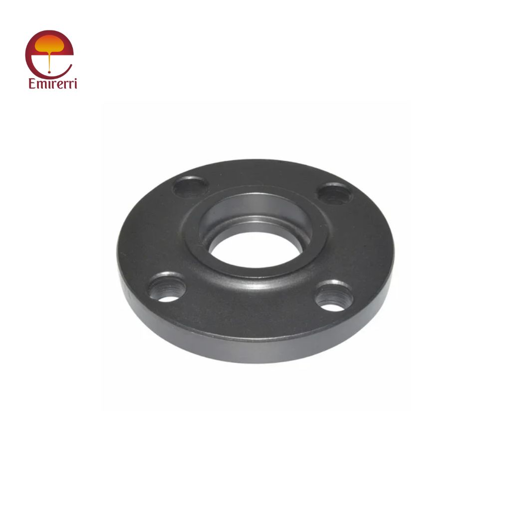
ASTM A105 Socket Weld Flange Manufacturer & Supplier
ASTM A105 Socket Weld Flange are manufactured from forged carbon steel and designed for small-bore, high-pressure piping systems. These flanges feature a recessed socket where the pipe is inserted and fillet welded, ensuring accurate pipe alignment and a smooth, flow-efficient bore. Socket Weld flanges are widely used in critical applications requiring high integrity and leak-proof joints such as oil & gas, power plants, chemical processing, and high-temperature steam lines.
Key Features
- Forged carbon steel for superior strength
- Ideal for small-size and high-pressure pipelines
- Smooth bore reduces turbulence and improves flow efficiency
- Precise pipe alignment ensures leak-proof joints
- Suitable for high-pressure and high-temperature services
- Available in RF & RTJ facing types
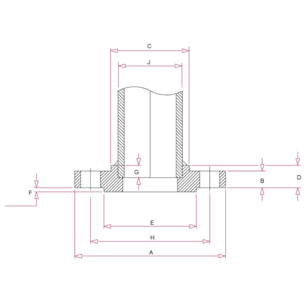
Socket Weld Flange Dimensions – Class 150 to Class 1500
Class 150 Socket Neck Flange Dimensions
| Size in Inch | Size in mm | Outer Dia. | Flange Thick. | Hub OD | Flange Length | RF Dia. | RF Height | Socket Depth | PCD | Socket Bore | No of Bolts | Bolt Size UNC | Machine Bolt Length | RF Stud Length | Hole Size | ISO Stud Size | Weight in kg |
|---|---|---|---|---|---|---|---|---|---|---|---|---|---|---|---|---|---|
| A | B | C | D | E | F | G | H | J | |||||||||
| 1/2 | 15 | 90 | 9.6 | 30 | 14 | 34.9 | 2 | 10 | 60.3 | 22.2 | 4 | 1/2 | 50 | 55 | 5/8 | M14 | 0.8 |
| 3/4 | 20 | 100 | 11.2 | 38 | 14 | 42.9 | 2 | 11 | 69.9 | 27.7 | 4 | 1/2 | 50 | 65 | 5/8 | M14 | 0.9 |
| 1 | 25 | 110 | 12.7 | 49 | 16 | 50.8 | 2 | 13 | 79.4 | 34.5 | 4 | 1/2 | 55 | 65 | 5/8 | M14 | 0.9 |
| 1 1/4 | 32 | 115 | 14.3 | 59 | 19 | 63.5 | 2 | 14 | 88.9 | 43.2 | 4 | 1/2 | 55 | 70 | 5/8 | M14 | 1.4 |
| 1 1/2 | 40 | 125 | 15.9 | 65 | 21 | 73 | 2 | 16 | 98.4 | 49.5 | 4 | 1/2 | 65 | 70 | 5/8 | M14 | 1.4 |
| 2 | 50 | 150 | 17.5 | 78 | 24 | 92.1 | 2 | 17 | 120.7 | 61.9 | 4 | 5/8 | 70 | 85 | 3/4 | M16 | 2.3 |
| 2 1/2 | 65 | 180 | 20.7 | 90 | 27 | 105 | 2 | 19 | 139.7 | 74.6 | 4 | 5/8 | 75 | 90 | 3/4 | M16 | 3.2 |
| 3 | 80 | 190 | 22.3 | 108 | 29 | 127 | 2 | 21 | 152.4 | 90.7 | 4 | 5/8 | 75 | 90 | 3/4 | M16 | 3.7 |
Class 300 Socket Neck Flange Dimensions
| Size in Inch | Size in mm | Outer Dia. | Flange Thick. | Hub OD | Flange Length | RF Dia. | RF Height | Socket Depth | PCD | Socket Bore | No of Bolts | Bolt Size UNC | Machine Bolt Length | RF Stud Length | Hole Size | ISO Stud Size | Weight in kg |
|---|---|---|---|---|---|---|---|---|---|---|---|---|---|---|---|---|---|
| A | B | C | D | E | F | G | H | J | |||||||||
| 1/2 | 15 | 95 | 12.7 | 38 | 21 | 34.9 | 2 | 10 | 66.7 | 22.2 | 4 | 1/2 | 55 | 65 | 5/8 | M14 | 1.2 |
| 3/4 | 20 | 115 | 14.3 | 48 | 24 | 42.9 | 2 | 11 | 82.6 | 27.7 | 4 | 5/8 | 65 | 75 | 3/4 | M16 | 1.4 |
| 1 | 25 | 125 | 15.9 | 54 | 25 | 50.8 | 2 | 13 | 88.9 | 34.5 | 4 | 5/8 | 65 | 75 | 3/4 | M16 | 1.4 |
| 1 1/4 | 32 | 135 | 17.5 | 64 | 25 | 63.5 | 2 | 14 | 98.4 | 43.2 | 4 | 5/8 | 70 | 85 | 3/4 | M16 | 1.8 |
| 1 1/2 | 40 | 155 | 19.1 | 70 | 29 | 73 | 2 | 16 | 114.3 | 49.5 | 4 | 3/4 | 75 | 90 | 7/8 | M20 | 2.7 |
| 2 | 50 | 165 | 20.7 | 84 | 32 | 92.1 | 2 | 17 | 127 | 61.9 | 8 | 5/8 | 75 | 90 | 3/4 | M16 | 3.2 |
| 2 1/2 | 65 | 190 | 23.9 | 100 | 37 | 105 | 2 | 19 | 149.2 | 74.6 | 8 | 3/4 | 85 | 100 | 7/8 | M20 | 4.6 |
| 3 | 80 | 210 | 27 | 117 | 41 | 127 | 2 | 21 | 168.3 | 90.7 | 8 | 3/4 | 90 | 110 | 7/8 | M20 | 5.9 |
Class 600 Socket Neck Flange Dimensions
| Size in Inch | Size in mm | Outer Dia. | Flange Thick. | Hub OD | Flange Length | RF Dia. | RF Height | Socket Depth | PCD | Socket Bore | No of Bolts | Bolt Size UNC | RF Stud Length | Hole Size | ISO Stud Size | Weight in kg |
|---|---|---|---|---|---|---|---|---|---|---|---|---|---|---|---|---|
| A | B | C | D | E | F | G | H | J | ||||||||
| 1/2 | 15 | 95 | 14.3 | 38 | 22 | 34.9 | 7 | 10 | 66.7 | 22.2 | 4 | 1/2 | 75 | 5/8 | M14 | 1.3 |
| 3/4 | 20 | 115 | 15.9 | 48 | 25 | 42.9 | 7 | 11 | 82.6 | 27.7 | 4 | 5/8 | 90 | 3/4 | M16 | 1.4 |
| 1 | 25 | 125 | 17.5 | 54 | 27 | 50.8 | 7 | 13 | 88.9 | 34.5 | 4 | 5/8 | 90 | 3/4 | M16 | 1.8 |
| 1 1/4 | 32 | 135 | 20.7 | 64 | 29 | 63.5 | 7 | 14 | 98.4 | 43.2 | 4 | 5/8 | 95 | 3/4 | M16 | 2.3 |
| 1 1/2 | 40 | 155 | 22.3 | 70 | 32 | 73 | 7 | 16 | 114.3 | 49.5 | 4 | 3/4 | 110 | 7/8 | M20 | 3.2 |
| 2 | 50 | 165 | 25.4 | 84 | 37 | 92.1 | 7 | 17 | 127 | 61.9 | 8 | 5/8 | 110 | 3/4 | M16 | 4.1 |
| 2 1/2 | 65 | 190 | 28.6 | 100 | 41 | 105 | 7 | 19 | 149.2 | 74.6 | 8 | 3/4 | 120 | 7/8 | M20 | 5.9 |
| 3 | 80 | 210 | 31.8 | 117 | 46 | 127 | 7 | 21 | 168.3 | 90.7 | 8 | 3/4 | 125 | 7/8 | M20 | 7.3 |
Class 1500 Socket Neck Flange Dimensions
| Size in Inch | Size in mm | Outer Dia. | Flange Thick. | Hub OD | Flange Length | RF Dia. | RF Height | Socket Depth | PCD | Socket Bore | No of Bolts | Bolt Size UNC | RF Stud Length | Hole Size | ISO Stud Size | Weight in kg |
|---|---|---|---|---|---|---|---|---|---|---|---|---|---|---|---|---|
| A | B | C | D | E | F | G | H | J | ||||||||
| 1/2 | 15 | 120 | 22.3 | 38 | 32 | 34.9 | 7 | 10 | 82.6 | 22.2 | 4 | 3/4 | 110 | 7/8 | M20 | 1.8 |
| 3/4 | 20 | 130 | 25.4 | 44 | 35 | 42.9 | 7 | 11 | 88.9 | 27.7 | 4 | 3/4 | 115 | 7/8 | M20 | 2.3 |
| 1 | 25 | 150 | 28.6 | 52 | 41 | 50.8 | 7 | 13 | 101.6 | 34.5 | 4 | 7/8 | 125 | 1 | M24 | 3.7 |
| 1 1/4 | 32 | 160 | 28.6 | 64 | 41 | 63.5 | 7 | 14 | 111.1 | 43.2 | 4 | 7/8 | 125 | 1 | M24 | 4.1 |
| 1 1/2 | 40 | 180 | 31.8 | 70 | 44 | 73 | 7 | 16 | 123.8 | 49.5 | 4 | 1 | 140 | 1 1/8 | M27 | 5.5 |
| 2 | 50 | 215 | 38.1 | 105 | 57 | 92.1 | 7 | 17 | 165.1 | 61.9 | 8 | 7/8 | 145 | 1 | M24 | 9.8 |
| 2 1/2 | 65 | 245 | 41.3 | 124 | 64 | 105 | 7 | 19 | 190.5 | 74.6 | 8 | 1 | 160 | 1 1/8 | M27 | 16.4 |
| 3 | 80 | 265 | 47.7 | 133 | N/A | 127 | 7 | 203.2 | N/A | 8 | 1 1/8 | 180 | 1 1/4 | M30 | 21.8 |
Chemical Composition (ASTM A105)
| Element | Composition (%) |
|---|---|
| Carbon (C) | 0.35 max |
| Manganese (Mn) | 0.60 – 1.05 |
| Silicon (Si) | 0.10 – 0.35 |
| Phosphorus (P) | 0.035 max |
| Sulfur (S) | 0.040 max |
| Copper (Cu) | 0.40 max |
| Nickel (Ni) | 0.40 max |
| Chromium (Cr) | 0.30 max |
| Molybdenum (Mo) | 0.12 max |
| Vanadium (V) | 0.08 max |
Mechanical Properties
| Property | Value |
|---|---|
| Tensile Strength | ≥ 485 MPa (70 ksi) |
| Yield Strength | ≥ 250 MPa (36 ksi) |
| Elongation | ≥ 22% |
| Hardness | ≤ 187 HB |
Physical Properties
| Property | Value |
|---|---|
| Density | 7.85 g/cm³ |
| Melting Point | ~1450°C |
| Modulus of Elasticity | 200 GPa |
| Thermal Conductivity | 60.5 W/m-K |
| Electrical Resistivity | 0.15 µΩ-m |
Types of ASTM A105 Socket Weld Flanges
- Standard Socket Weld Flange
- Socket Weld RTJ Flange
- Socket Weld Reducing Flange
- Socket Weld Orifice Flange
- Raised Face (RF) Socket Weld Flange
Applications
- Oil & Gas Transmission Pipelines
- Chemical & Petrochemical Plants
- High-Pressure Steam Piping
- Power Plants & Boilers
- Water Treatment Units
- Hydraulic & Marine Systems
- High-Temperature & High-Pressure Services
Reviews
There are no reviews yet.